User Tools
sensors:lsm111
This is an old revision of the document!
Table of Contents
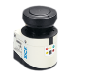
Sick LSM111 - LIDAR
The Laser scanner LSM111 from the company Sick. All information is copied from this web.
The LSM on the armadillo currently has 193.167.0.1 as IP
LSM 111 Manual
Specifications
| Index |
|---|
| Functional data |
| General data |
Functional data
| Minimum | Typical | Maximum | |
|---|---|---|---|
| Scan angle | 270° | ||
| Scanning frequency | 25 Hz | 50 Hz | |
| Remission | 10% | Several 1,000 %(1*) (reflectors) | |
| Angular resolution | |||
| - With 25 Hz | 0.25° | 0.5° | |
| - With 50 Hz | 0.5° | ||
| Measurement error 1st reflected pulse(2*) | |||
| - Systematic error | ± 30 mm (± 1.18 in) | ± 40 mm (± 1.58 in) | |
| - Temperature drift | 0 mm/°C (0 in/°F) | 0.32 mm/°C (0.007 in/°F) | |
| - Statisticalerror(1σ) | 12 mm (0.47 in) | 20 mm (0.79 in) | |
| Immunity to external light | 40 klx | ||
| Evenness of the scan field (25 Hz) | |||
| - Cone | ±0.5° | ±1° | |
| - Inclination | ±1° | ±–2° | |
| Distance from mirror axis of rotation (zero point on the X and Y axis) to the rear of the device | 55 mm (2.17 in) | ||
| Distance between centre of the scan plane and the bottom edge of the housing | 116 mm (4.57 in) | ||
| Distance measuring range | |||
| - LMS100/LMS111/LMS122/LMS123 | 0.5 m (1.64 ft) | 20 m (65.62 ft) | |
| - LMS151 | 0.5 m (1.64 ft) | 50 m (164,04 ft) | |
| Hardware blanking window | 0 m (0 ft) | 15 m (49.21 ft) | |
| - Step width | 1 m (3.28 ft) | ||
| Power-up delay | 60 s | ||
| - Of a configured device | 15 s | ||
| Configurable restart after | 2 s | 60 s | |
General data
| Minimum | Typical | Maximum | |
|---|---|---|---|
| Laser protection class | Laser class 1 according IEC 60825H1 (2007H3) (complies with 21 CFR 1040.10 with the exception of the deviations as per Laser Notice No. 50, July 26, 2001) | ||
| Enclosure rating | As per EN 60529 (1991H10); A1 (2002H02) | ||
| - LMS100/LMS122/LMS123 | IP 65 | ||
| - LMS111/LMS151 | IP 67 | ||
| Protection class | III as per EN 50178 (1997H10) | ||
| EMC test | As per EN 61000H6H2 (2005H08), EN 61000H6H3 (2007H03) | ||
| Electrical safety | As per EN 50178 (1997H10) | ||
| Operating temperature range | |||
| - LMS100/LMS122/LMS123 | 0 °C (32 °F) | +50 °C (122 °F) | |
(1*)(2*)(3*)
| (1*) Corresponds to Diamond Grade 3000XTM (approx. 1,250 cd/lx × m2). | |||
| (2*) The time after the first reflected pulse from which measurement can be performed with full accuracy is dependent on the target that reflected the first reflected pulse. | |||
| (3*) Without fixing screws and projection of cable glands with system plug mounted. |
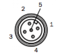
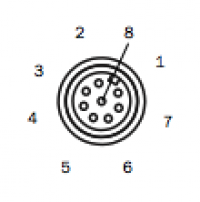
Cable connection
sensors/lsm111.1347281773.txt.gz · Last modified: 2021/08/14 04:20 (external edit)


