User Tools
robots:hako:hardware:esx_3xl
Table of Contents
ESX 3XL
Documentation from Sensor-Technik Wiedemann GmbH
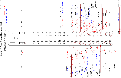
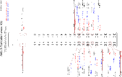
Connectors KS1 KS2
Downloads in English.
IO List for ESX on the Hako
Connection list for the ESX 3XL computer in the AMS
ESX 3XL Connection list (45 KB .xls)
Diagrams
Click at the diagrams to get a bigger picture and a zoom-function:
AMS (1) Test Cable Harness, KS1
AMS (1) Test Cable Harness, KS2
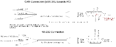
Can / RS232 Connection
Connector in ESX 3XL, view towards ESX 3XL
ESX 3XL connectors: Cable connector (socket) seen from front (mating side)
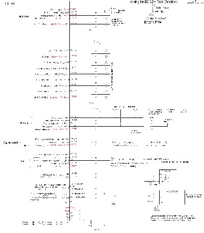
ESX 3XL IO for Hako
For test of the Engine RPM, Output Switches, CVT and Steering modules something like the following hardware will be needed.
IO for ESX Description
Inputs
Channel 1 (KS1 pin 70) : Extra engine speed input. (PNP 12 V).
Channel 2 (KS1 pin 12) : Extra prop shaft (CVT) input. (PNP 12 V).
Channel 5 (KS1 pin 69) : Prop shaft (CVT) quadrature encoder A. (PNP 12 V).
Channel 6 (KS1 pin 11) : Prop shaft (CVT) quadrature encoder B. (PNP 12 V).
Channel 7 (KS1 pin 30) : Engine speed. (PNP 12 V).
??Channel 8 (KS1 pin 49) : CVT Neutral. Switch to 12 V (i.e. PNP type).
Channel 9 (KS1 pin 68) : Steering angle left. (Potentiometer).
Channel 10 (KS1 pin 10) : Steering angle right. (Potentiometer).
Outputs
Channel 2 (KS1 pin 33) : Aux Rear (hydraulics).
Channel 3 (KS1 pin 51) : Lights (head).
Channel 4 (KS1 pin 52) : Horn.
Channel 6 (KS1 pin 14) : Reversing Lights.
Channel 7 (KS1 pin 71) : Flashing Light Left (indicator light).
Channel 8 (KS1 pin 72) : Flashing Light Right (indicator light).
Channel 9 (KS2 pin 49) : Steering reference.
Channel 13 (KS2 pin 50) : CVT Speed reference.
Channel 16 (KS2 pin 70) : PTO Rear.
Channel 17 (KS2 pin 51) : Engine speed reference.
Sensor supply
Uext1 (KS1 pin 66) ??Supply for steering angle potentiometers?
AGND (for Uext1) (KS1 pin 47)
Supply for output groups
+UB1 (KS1 pin 5)
+UB2 (KS2 pin 5)
+UB3 (KS2 pin 2)
RS-232
TXD (KS1 pin 44)
RXD (KS1 pin 63)
CAN1 (interface to NavCom)
CAN1_H (KS1 pin 7 / 8)
CAN1_L (KS1 pin 26 / 27)
  Consider whether both pins should be connected (what would be the easiest
  in case the test pattern generator CAN2 should be connected/disconnected).
CAN2 (generating test pattern (commands))
CAN2_H (KS1 pin 45 or 46)
CAN2_L (KS1 pin 64 or 65)
  Idea: write task which will output a test pattern - not necessarily listening
  to any reports. If complicated tests (many packets) are needed it seems the
  generation of CAN messages should be automated - the ESX 3XL seems to be the
  only available device which can generate CAN message patterns).
Supply for computer
GND (KS1 pin 2)
+UE (KS1 pin 6)
D+ (KS1 pin 25) ??Will this be necessary for this test?
??Consider sequencing input for test purposes? The RS-232 or the CAN bus should probably be used instead.
robots/hako/hardware/esx_3xl.txt · Last modified: 2021/08/14 04:21 (external edit)


