User Tools
This is an old revision of the document!
Table of Contents
Frobobox
 This is the computer on the Armadillo Scout. It is an industrial grade computer built in IP66 aluminum box. It is using Ubuntu as operatingsystem and can be accessed via the built in Wifi.
Frobobox documentation from SDU
This documentation is updated when changes are made to our FroboBox.
Here is the different configurations for the Frobobox to work in Hohenheim
Diagram
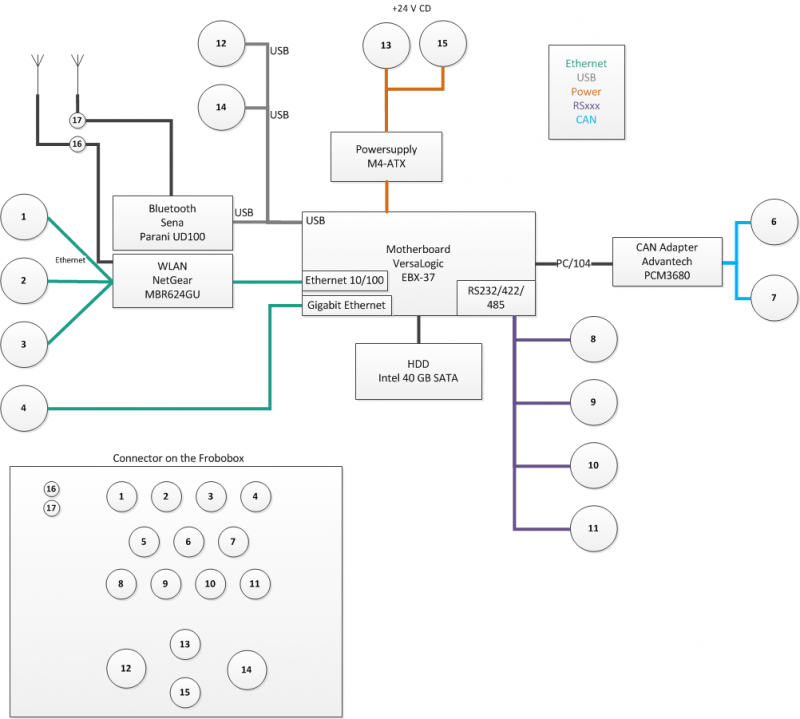
Connection List
<columns 100% first column attributes 50% second column attributes →
| Plug | Type |
|---|---|
| 1 | ETHERNET 10/100 |
| 2 | ETHERNET 10/100 |
| 3 | ETHERNET 10/100 |
| 4 | GIGABIT ETHERNET |
| 5 | Analog Input |
| 6 | CAN |
| 7 | CAN |
| 8 | RS232 |
| 9 | RS232 |
| 10 | RS232/422/485 |
| 11 | RS232/422/485 |
| 12 | USB |
| 13 | +24 VDC |
| 14 | USB |
| 15 | Power 2 - AUX/Display - not defined yet |
| 16 | WI-FI Antenna |
| 17 | Bluetooth Antenna |
<newcolumn>
| Plug | Currently connected to |
|---|---|
| 1 | SICK LMS-111 |
| 2 | Trimble AgGPS542 |
| 3 | NC |
| 4 | HoWLAN / NC |
| 5 | NC |
| 6 | NC |
| 7 | NC |
| 8 | Motorcontroller left/right |
| 9 | Motorcontroller left/right |
| 10 | NC |
| 11 | NC |
| 12 | ?? |
| 13 | Power |
| 14 | ?? |
| 15 | NC |
| 16 | WI-FI Antenna |
| 17 | Bluetooth Antenna |
</columns>
Connector description
The connectors used at the FroboBox is the industrial connector standard M12.
RS232 (M12 a-coded - 8pins female connector)
(8)+(9) on block diagram.
There are no configuration jumpers for COM1 and COM2 since they only operate in RS-232 mode.
 | pin - 1 | white | +5V | |
| pin - 2 | brown | +12V | ||
| pin - 3 | green | RXD | COM1 J18-3 , COM2 J18-12 | |
| pin - 4 | yellow | CTS | COM1 J18-6 , COM2 J18-15 | |
| pin - 5 | grey | GND | COM1 J18-9 , COM2 J18-18 | |
| pin - 6 | pink | RTS | COM1 J18-4 , COM2 J18-13 | |
| pin - 7 | blue | TXD | COM1 J18-5 , COM2 J18-14 | |
| pin - 8 | red | GND |

RS232/422/485 (M12 a-coded - 8pins female connector)
(10)+(11) on block diagram.
Use CMOS Setup on the Versalogic mainboard to select between RS-232 4-wire, RS-422, and RS485 operating modes for COM3 and COM4. Jumper block V3 (see datasheet MEBX37-1.pdf for description) is used to enable the RS-422/485 termination resistor for COM3 and COM4. Jumper V3[1-2] enables the RS-422/485 termination resistor for COM3, and jumper V3[3-4] for COM4. The termination resistor should be enabled for RS-422 and the RS-485 endpoint station. It should be disabled for RS-232 and the RS-485 intermediate station.
| | pin - 1 | white | +5V | |
| pin - 2 | brown | +12V | ||
| pin - 3 | green | RXD / RXD- | COM3 J18-23 , COM4 J18-30 | |
| pin - 4 | yellow | CTS / RXD+ | COM3 J18-24 , COM4 J18-31 | |
| pin - 5 | grey | GND | COM3 J18-22 , COM4 J18-29 | |
| pin - 6 | pink | RTS / TXD+ | COM3 J18-20 , COM4 J18-27 | |
| pin - 7 | blue | TXD / TXD- | COM3 J18-21 , COM4 J18-28 | |
| pin - 8 | red | GND |
Analog Inputs (M12 a-coded - 8pins female connector)
(5) on block diagram.
Four analog to digital converters are available on the motherboard
CAN (M12 a-coded - 8pins female connector - based on CANopen)
(6)+(7) on block diagram These ports utilizes a 5-Pin M12 CANopen shown below.
 | pin - 1 | brown | CAN-Shield | |
| pin - 2 | white | +12V | ||
| pin - 3 | blue | GND | box header pin 5 | |
| pin - 4 | black | CAN-High | box header pin 4 | |
| pin - 5 | grey | CAN-Low | box header pin 3 |

ETHERNET 10/100 (M12 d-coded - 4 pins female connector)
(1)+(2)+(3) on block diagram.
 | pin - 1 | yellow | Receive- | RJ-45 pin 6 |
| pin - 2 | white | Transmit- | RJ-45 pin 3 | |
| pin - 3 | orange | Receive+ | RJ-45 pin 2 | |
| pin - 4 | blue | Transmit+ | RJ-45 pin 1 |

GIGABIT ETHERNET (M12 a-coded - 8 pins female connector)
(4) on block diagram.
| | pin - 1 | orange-white | TX_D1+ | RJ-45 pin 1 |
| pin - 2 | orange | TX_D1- | RJ-45 pin 2 | |
| pin - 3 | green-white | RX-D2+ | RJ-45 pin 3 | |
| pin - 4 | green | RX D2- | RJ-45 pin 6 | |
| pin - 5 | brown-white | BI D4+ | RJ-45 pin 7 | |
| pin - 6 | brown | BI D4- | RJ-45 pin 8 | |
| pin - 7 | blue-white | BI-D3- | RJ-45 pin 5 | |
| pin - 8 | blue | BI-D3+ | RJ-45 pin 4 |

USB


Power Connector
1: GND (black), 2:GND(blue), 3:VCC(brown),4:VCC(White)
 | pin - 1 | Black | GND |
| pin - 2 | Blue | GND | |
| pin - 3 | Brown | +24 VCC | |
| pin - 4 | White | +24 VCC |
Power connector - AUX/Display
Currently power connector.
| pin - 1 | Black | GND |
| pin - 2 | Blue | GND | |
| pin - 3 | Brown | +24 VCC | |
| pin - 4 | White | +24 VCC |
Power Cable
 | pin - 1 | Black | Not connected |
| pin - 2 | Blue | GND | |
| pin - 3 | Brown | Not connected | |
| pin - 4 | White | +24 VCC |

Wifi/Bluetooth Antenna
The antenna for the Wifi and Bluetooth is identical. Looks like: TL-ANT2408CL from the company TP-Link. The antenna has a RP-SMA Male connection.
Download data sheet of the TL-ANT2408CL (194 KB)
Scaffold
The internal scaffold for the FroboBox consists of three aluminum plates separated by 35 mm spacers. The lower plate is cut in shape to fit exactly into the enclosure and the two top plates are cut in dimensions 150 x 215 mm to fit the motherboard. When mounting the motherboard it is important to align it to the edge to make room for the RJ-45 connections. Get printable drawings of Top deck, middle deck and lower deck (A3).
Wirering
A splitter PCB is needed between the four serial connectors and the J18 connector on the motherboard. This can be done with the big and clumsy PCB that is delivered with the motherboard or with this nice and small PCB.
| COM1 | COM2 | COM3 | COM4 | |
|---|---|---|---|---|
| 1 | pink | blue | grey | grey |
| 2 | green | green | pink | blue |
| 3 | yellow | yellow | yellow | yellow |
| 4 | blue | pink | green | green |
| 5 | grey | grey | blue | pink |
| 6 | white | white | white | white |
| 7 | red | red | red | red |
| 8 | brown | brown | brown | brown |
| 9 | NC | NC | NC | NC |
| 10 | NC | NC | NC | NC |
Component list
| Component | Part | Link to buy | Link to manufacturer | PDF documentation | Manual |
|---|---|---|---|---|---|
| Motherboard | VersaLogic EBX37 Mamba EBX-formfactor single board computer with PCI104 carrier/connector. Intel Core2 Duo 2.0Ghz. 2GB DDR2 RAM. | VersaLogic | Versilogic Mamba | EBX37 Manual | |
| Harddrive | Intel 40GB SSD SATA | Dustin | Intel | Harddisk | X25V Manual |
| CAN adaptor | Advantech PCM3680 PC/104 2-port CAN module | Tri-m | PCM 3680 | Manual | |
| Power supply | M4-ATX, 250w output, 6v to 30v wide input Intelligent Automotive DC-DC Car PC Power Supply | Mini-Box | M4-ATX | Manual | |
| Ethernet/WiFi | Netgear MBR624GU | Netgear | Netgear | Manual | |
| Bluetooth | Parani-UD100 | Sena - Parani | doc | man | |
| Enclosure | ALUMINIUM 230X330X180MM | Farnell | Rose | RoseBox | Datasheet |
| Display | Suggestion… | RS | |||
| 8-pin connector | M12 a coded Female for (5)+(8)+(9)+(10)+(11) | Phoenix | 8 Connector | ||
| 8-pin connector | M12 a coded Female for (4) | Phoenix | 8 Connector | ||
| 5-pin connector | M12 a coded Female for (6)+(7) | Phoenix | 5 Connector | ||
| 4-pin connector | M12 a coded Female for (1)+(2)+(3) | Phoenix | 4 Connector | ||
| USB connector | USB Buccaneer panel for (12)+(14) | RS | USB Connector | ||
| Sealing cap | panel sealing cap for (12)+(14) | RS | Sealing cap | ||
| RP SMA connector | Wifi/Bluetooth antenna(16)+(17) | ||||
| Wifi/Bluetooth antenna | TP-Link | antenna | |||
<task> TITLE: Document SMA connector and cable PRIORITY: Middle ESTIMATE: 2h PROGRESS: 0% ASSIGNED: Karina DESCRIPTION: Find the correct type of SMA connector and document here like the other connector. Important part is farnell, RS or conrad number. </task>
