User Tools
Table of Contents
This page has been copied from http://www.roboteq.com/technology/roboteq-motor-controlers-technology, to make sure the information is not lost.
NxtGen Brushed DC Motor Controllers
All Roboteq controllers are high performance, microcontroller-based motor controllers, loaded with numerous features and operating modes. Yet, for all their sophistication, the controllers are very simple to install and operate. Their many configuration options are programmed using PC utility with a convenient Graphical User Interface. Once programmed, the configuration data are stored permanently in the controllers' nonvolatile memory, eliminating the need for cumbersome and unreliable jumpers.
The Roboteq controllers are fitted with many safety features ensuring a secure power-on start, automatic stop in case of command loss, overcurrent protection, and overheat protection. Temperature sensors automatically adjusts the Amps limit in case of overheating.
This section discusses in general terms the main features of the Roboteq controllers. Not all features apply to all controller models. The exact specifications and features list can be found in the Datasheet and User's Manuals for each product
Single Power Supply Operation
All Roboteq controllers, except the AX500, include a DC/DC converter that will generate all internal voltages for the microcomputer, logic and motor drivers, from the main +12 to +40V or 10 to +50V (depending on models). As a result, the controller will turn On as soon as its Battery Wires are connected to the battery. In order to turn On and Off the controller without the need for a bulky and expensive switch or relay on the high current wires, the controllers use a Power Control wire to enable or disable the internal DC/DC converter. When left unconnected, the DC/DC converter is On. When grounded, the DC/DC converter is Off. The Power Control wire can also be used to feed a stable 12V supply to the controller so that it will continue to operate if and when the main batteries’ voltage dips below the undervoltage limit.
Multiple Input Modes
The controllers’ multiple command input modes - R/C Radio Pulse Width, Serial Port or Analog - make them uniquely interfaceable to all types of microcontrollers, remote control radios, or other command devices.
R/C Radio mode
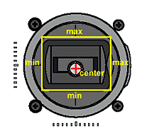
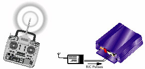 R/C Radio is the simplest and least expensive method to build and operate a remote controlled robot. In this mode, the controller supports many configurable options, including joystick calibration of min, max and center positions and deadband adjustment.
Serial Port (RS232) mode
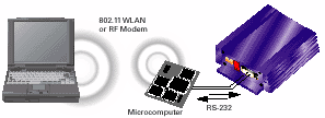 Using the serial mode, the controller may be interfaced to a microcomputer for autonomous operation. Using a wireless modem or wireless network adapter (802.11), more advanced remote control operations are possible, including remote control via the Internet.
Analog mode
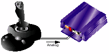
A simple 0-5V analog control mode is also provided for direct connection to potentiometers or analog joysticks.
On all NxtGen motor controller, the range of the analog input (Min, Max and Center) can be calibrated to meet the the joystick's range.
Programmable Command Corrections
The Roboteq controllers can be configured to automatically correct and compute an adjusted motor command value.
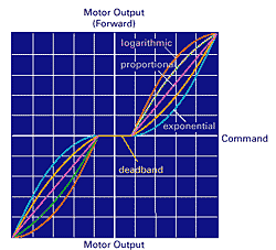 Programmable deadband adjustment
The controllers allow a selectable amount of joystick motion from the center position before they begins applying power to the motors. This feature ensures a safe start and smooth operation for the robot.
Exponentiation adjustment
After the joystick moves past the deadband position, the controllers can be set to add an increasing (exponential) or decreasing (logarithmic) amount of power to the motor. This allows the operator to set the robot’s best driving characteristic for a particular use.
Joystick calibration (R/C mode only)
With the push of a button, the min, max and center positions of the R/C joysticks can be captured and stored in the controller. Because of this feature, the controllers will deliver on the full joystick travel position and will always start at a safe idle position.
Multiple Motor Command Modes
Roboteq controllers may be connected to two motors which will react to commands received on two input channels. Using these two channel inputs, the motors can be commanded independently or in a combined fashion to accommodate the most common drive and steering methods in robotic vehicles.
Independent Speed command In this mode, each of the two motors is commanded independently of the other. This operating mode is best suited for generic motor control applications.
Mixed Speed/Steering command In this mode, the motors work in combination to move and turn a vehicle by combining the forward/reverse command information and the left/right steering information. This mode of operation provides a cost effective method for moving and steering tank-style robots and underwater vehicles.
Position Commands In this mode, each channel independently controls the angular position of one motor. The heavy duty servos built in this way can be used to control throttle, breaks, and steering of life-size vehicles or animate any large and heavy structure.
Multiple Motion Modes
For each channel, the Roboteq controllers supports multiple motion control modes:
Open Loop Speed mode In this mode, the controller delivers an amount of power proportional to the command information. The actual motor speed is not measured. This mode is adequate for most applications where the operator maintains a visual contact with the robot.
Closed Loop Speed mode
In this mode, an analog tachometer or optical encoder measures the actual motor speed. If the speed changes because of changes in load, the controller automatically compensates the power output. This mode is preferred in precision motor control and autonomous robotic applications.
Closed Loop Position mode
In this mode, the axle of a geared down motor is coupled to a potentiometer that is used to compare the angular position of the axle versus a desired position. This unique feature makes it possible to build ultrahigh torque “jumbo servos” that can be used to drive steering columns, robotic arms,animatronics, life-size models and other heavy loads.
MicroBasic Scripting Language
The latest generation of Roboteq controllers incorporate a simple but very fast and powerful scripting language, allowing new function to easily be added by the user. The feature is fully described in the MicroBasic page.
Dual Channel or Single Channel
All controllers may be ordered in Dual or Single Channel versions. The Single Channel controllers are identical to the Dual Channel except that the output transistors of both channels are perfectly synchronized and thus allow the motor output leads to be wired in parallel and thus drive twice the amps into a single load.
Optical Encoder Inputs
Available on most controller models, optical incremental encoders are a mean for capturing speed and traveled distance on a motor. Counting the pulses tells the application how many revolutions, or fractions of, the motor has turned. Rotation velocity can be determined from the time interval between pulses, or by the number of pulses within a given time period. Because they are digital devices, incremental encoders will measure distance and speed with perfect accuracy.
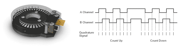 To count up or down according to motor direction, quadrature encoders have dual channels, A and B, which are electrically phased 90° apart. Direction of rotation can be determined by monitoring the phase relationship between the two channels.
The encoder's speed measurement makes it possible to use the controller in closed loop speed mode without the need for calibration and drifting problems that can occur using analog tachometer. The pulse count feature is very useful to measure the actual traveled distance by the robot. It can also be used to perform sophisticated and high precision positioning algorithms. Hall Sensor Inputs
On Brushless Motor controllers, an input connector or headr is provided for the motor's hall sensors. The sensor's primary funtion is to detect the position of the rotor and instruct the controller to energize in the motor coils in sequence in order to induce rotation. On advance models, the hall sensors are also used to measure speed and the distanced travelled by the motor. Closed loop speed and position modes use this information for feedback.
RC Servo Output
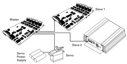
The AX3500 is equipped with an RC pulse output port for driving RC servos or additional Roboteq controllers (only in RS232 mode). A single AX3500 can comtrol up to 8 devices in this way as shown in the figure below. Note that servos require and external Power Supply.
Ultra Efficient Power Output Stages
All controllers includes two high-efficiency Power Output stages which can operate up to 50 VDC (higher on some products). Each of these stages supports the following advanced features:
Precise, Smooth, Forward/Reverse Control
High efficiency MOSFET “H-Bridges” are used for full forward and reverse operation. The controller uses Pulse Width Modulation at 16kHz to generate smooth, variable output power in as little as 0.5% increments.
Ultra-Low "On" resistance
This parameter refers to the conductivity of the MOSFET transistors when they are turned on. A low “On” value results in less heat generated by the transistors for a given current flow. It is the principal metric for comparing the efficiency - and real power handling capability - of one controller type over another. The power generated inside the transistors is computed using the formula P = I x I x R. The published “On” resistance on all Roboteq web pages and documents is the the total resistance that is between the motor leads and the battery.
Current Limiting and Programmable Acceleration
A sensor measures the actual current delivered to the motors and automatically reduces the power if the current goes over the preset limits during extended periods of time. Temperature sensors located on each heatsink will cause the controller to adjust the maximum allowed Amps in case of controller overheat. This feature eliminates the need for oversizing the controller and allows the controllers to perform as better than products without current limitation.
Controlled Motor Acceleration
The controllers can also be configured to automatically “smooth” command changes (from stop to full speed, for example) to avoid sudden overloads on the controller, the batteries and/or the robot’s mechanical components. The controller’s programmable acceleration feature will automatically limit abrupt speed changes to preset user values. Acceleration and Deceleration rate can be set separately on Roboteq's most recent products.
Over and Undervoltage Protection
All Roboteq controllers monitor the battery voltage and will shut off the power stage when unsafe conditions are present. This feature is particularly useful during rapid decelerations as the regenerated current that is trying to flow back to the battery, may cause the voltage to rise to dangerous levels in certain conditions.
Synchronous Rectification
This technique uses actively commanded MOSFETs, instead of diodes, to route the reverse current that flows back from an inductive load (such as a motor) as it is switched off during the Pulse Width Modulation cycles. Practically, this results in higher power efficiency and very direct control of speed, particularly during deceleration thanks to a braking effect. Synchronous Rectification also allows regeneration into the battery during deceleration. This feature is implemented on all Roboteq controllers except the AX500.
Heavy Duty Power Wiring and Connectors
All Roboteq controllers feature power connectors or wires properly sized to the current handling of a given model.
| Connection Type | Benefits |
|---|---|
| AWG8 wires | Highest current handling |
| Fast-on tab | Easy disconnect, high current handling, proven reliability in automotive, tight connection |
| Screw Terminal | Simple and reliable connection |
Enclosures and Cooling
All Roboteq controllers feature alluminum heat sink for dissipating the heat generated inside the power MOSFETs. Open-frame models use an aluminum heatsink located under the board or an optional bottom plate for conduction cooling. Enclosed model versions are mounted inside an aluminum extrusion that serves as a heatsink.
Digital I/O and Analog Inputs
All controllers feature a convenient 15-pin or 25-pin connector (depending on model) is used for the following low voltage connections:
- Digital Inputs which may be used for emergency stop, invert direction, limit switch, etc.
- Pulse/RC inputs for Radio or for sensors with PWM output
- Analog inputs for connecting joystick and/or position/speed feedback sensor
- 1A solid-state switched output(s) for controlling a brake, clutch, weapon, field excitation relay or other device.
- A regulated 5V supply output for powering the R/C radio (Battery Eliminator Circuit).
Often, an input can be used as Analog, Digital or RC input. Details of quantity, types and possible use is shown in the product datasheet.
PC-Based Configuration and Monitoring Utility
Roboteq controllers are delivered with a PC utility and connection cable that will allow you to perform the following functions:
- Read and set the programmable parameters with a user-friendly graphical interface
- Obtain the controller’s software revision and date
- Send precise commands to the motors
- Read and chart real-time current consumption value, motor temperature and/or battery voltage
- Save controller operating data to disk for analysis with MS Excel
Using the PC and an internet connection, it is also possible to download and install software updates to the controller in order to improve existing features or enable new ones as they become available. This unique capability keeps the controllers from ever becoming obsolete.
Screen shot of Parameters Configuration and Software Updating Utility
Updating the controller with the latest software is a very simple and quick point-and-click procedure requiring no special computer or electronics skill. Upon request, Roboteq can also perform custom modifications to the embedded software to meet specific user’s requirements.
