User Tools
This is an old revision of the document!
Table of Contents
ESX 3XL
Mainboard - Hardware - Pin assignment (sorted by pin numbers)
Download “Pin assignment (sorted by pin numbers)” as pdf (82 KB)
Connectors (male) of ESX-3XL (KS1 and KS2) (by number)
Pin assignment of KS1 (Pins sorted by pin numbers)
For a table where pins are sorted by funktion, look here.
| Connector | Pin | Type | CAD signal name | Description | Mainboard | Expansion slot A..F |
|---|---|---|---|---|---|---|
| KS1 | 1 | Pwr | POWER_C_PIN14 | Expansion slot C - IO pin 14 (e.g. power supply ) | x | |
| KS1 | 2 | Pwr | GND | Ground mainboard | x | |
| KS1 | 3 | Pwr | POWER_A_PIN14 | Expansion slot A - IO pin 14 (e.g. power supply ) | x | |
| KS1 | 4 | Pwr | POWER_B_PIN14 | Expansion slot B - IO pin 14 (e.g. power supply ) | x | |
| KS1 | 5 | Pwr | +UB1 | Power supply pin for outputs 1..8 (High-Side 4 A) | x | |
| KS1 | 6 | Sig | +UE | Power supply electronic | x | |
| KS1 | 7 | Sig | CAN1_H | CAN bus 1 (high) | x | |
| KS1 | 8 | Sig | CAN1_H | CAN bus 1 (high) | x | |
| KS1 | 9 | Sig | AIN_DIN14 | Multi-functional input 14 | x | |
| KS1 | 10 | Sig | AIN_DIN10 | Multi-functional input 10 | x | |
| KS1 | 11 | Sig | AIN_DIN6 | Multi-functional input 6 | x | |
| KS1 | 12 | Sig | AIN_DIN2 | Multi-functional input 2 | x | |
| KS1 | 13 | Sig | HS4A_PWM_MUT5 | High-Side PWM output 5 (4 A) | x | |
| KS1 | 14 | Sig | HS4A_PWM_MUT6 | High-Side PWM output 6 (4 A) | x | |
| KS1 | 15 | Sig | BABY_A_PIN10 | Expansion slot A - IO pin 10 | x | |
| KS1 | 16 | Sig | BABY_A_PIN6 | Expansion slot A - IO pin 6 | x | |
| KS1 | 17 | Sig | BABY_A_PIN2 | Expansion slot A - IO pin 2 | x | |
| KS1 | 18 | Sig | BABY_B_PIN11 | Expansion slot B - IO pin 11 | x | |
| KS1 | 19 | Sig | BABY_B_PIN7 | Expansion slot B - IO pin 7 | x | |
| KS1 | 20 | Sig | BABY_B_PIN3 | Expansion slot B - IO pin 3 | x | |
| KS1 | 21 | Sig | BABY_C_PIN12 | Expansion slot C - IO pin 12 | x | |
| KS1 | 22 | Sig | BABY_C_PIN8 | Expansion slot C - IO pin 8 | x | |
| KS1 | 23 | Sig | BABY_C_PIN4 | Expansion slot C - IO pin 4 | x | |
| KS1 | 24 | Sig | PWR_OPT_C_PIN13 | Expansion slot C - IO pin 13 (e.g. free-wheeling current) | x | |
| Connector | Pin | Type | CAD signal name | Description | Mainboard | Expansion slot A..F |
| KS1 | 25 | Sig | D+ | Ignition | x | |
| KS1 | 26 | Sig | CAN1_L | CAN bus 1 (low) | x | |
| KS1 | 27 | Sig | CAN1_L | CAN bus 1 (low) | x | |
| KS1 | 28 | Sig | AIN_DIN15 | Multi-functional input 15 | x | |
| KS1 | 29 | Sig | AIN_DIN11 | Multi-functional input 11 | x | |
| KS1 | 30 | Sig | AIN_DIN7 | Multi-functional input 7 | x | |
| KS1 | 31 | Sig | AIN_DIN3 | Multi-functional input 3 | x | |
| KS1 | 32 | Sig | HS4A_PWM_MUT1 | High-Side PWM output 1 (4 A) | x | |
| KS1 | 33 | Sig | HS4A_PWM_MUT2 | High-Side PWM output 2 (4 A) | x | |
| KS1 | 34 | Sig | BABY_A_PIN11 | Expansion slot A - IO pin 11 | x | |
| KS1 | 35 | Sig | BABY_A_PIN7 | Expansion slot A - IO pin 7 | x | |
| KS1 | 36 | Sig | BABY_A_PIN3 | Expansion slot A - IO pin 3 | x | |
| KS1 | 37 | Sig | BABY_B_PIN12 | Expansion slot B - IO pin 12 | x | |
| KS1 | 38 | Sig | BABY_B_PIN8 | Expansion slot B - IO pin 8 | x | |
| KS1 | 39 | Sig | BABY_B_PIN4 | Expansion slot B - IO pin 4 | x | |
| KS1 | 40 | Sig | PWR_OPT_B_PIN13 | Expansion slot B - IO pin 13 (e.g. free-wheeling current) | x | |
| KS1 | 41 | Sig | BABY_C_PIN9 | Expansion slot C - IO pin 9 | x | |
| KS1 | 42 | Sig | BABY_C_PIN5 | Expansion slot C - IO pin 5 | x | |
| KS1 | 43 | Sig | BABY_C_PIN1 | Expansion slot C - IO pin 1 | x | |
| KS1 | 44 | Sig | TXD | RS232 1 (TxD) | x | |
| KS1 | 45 | Sig | CAN2_H | CAN bus 2 (high) | x | |
| KS1 | 46 | Sig | CAN2_H | CAN bus 2 (high) | x | |
| KS1 | 47 | Sig | AGND | Analog ground (Uext1) | x | |
| KS1 | 48 | Sig | AIN_DIN12 | Multi-functional input 12 | x | |
| KS1 | 49 | Sig | AIN_DIN8 | Multi-functional input 8 | x | |
| KS1 | 50 | Sig | AIN_DIN4 | Multi-functional input 4 | x | |
| KS1 | 51 | Sig | HS4A_PWM_MUT3 | High-Side PWM output 3 (4 A) | x | |
| KS1 | 52 | Sig | HS4A_PWM_MUT4 | High-Side PWM output 4 (4 A) | x | |
| KS1 | 53 | Sig | BABY_A_PIN12 | Expansion slot A - IO pin 12 | x | |
| KS1 | 54 | Sig | BABY_A_PIN8 | Expansion slot A - IO pin 8 | x | |
| KS1 | 55 | Sig | BABY_A_PIN4 | Expansion slot A - IO pin 4 | x | |
| KS1 | 56 | Sig | PWR_OPT_A_PIN13 | Expansion slot A - IO pin 13 (e.g. free-wheeling current) | x | |
| KS1 | 57 | Sig | BABY_B_PIN9 | Expansion slot B - IO pin 9 | x | |
| KS1 | 58 | Sig | BABY_B_PIN5 | Expansion slot B - IO pin 5 | x | |
| KS1 | 59 | Sig | BABY_B_PIN1 | Expansion slot B - IO pin 1 | x | |
| KS1 | 60 | Sig | BABY_C_PIN10 | Expansion slot C - IO pin 10 | x | |
| Connector | Pin | Type | CAD signal name | Description | Mainboard | Expansion slot A..F |
| KS1 | 61 | Sig | BABY_C_PIN6 | Expansion slot C - IO pin 6 | x | |
| KS1 | 62 | Sig | BABY_C_PIN2 | Expansion slot C - IO pin 2 | x | |
| KS1 | 63 | Sig | RXD | RS232 1 (RxD) | x | |
| KS1 | 64 | Sig | CAN2_L | CAN bus 2 (low) | x | |
| KS1 | 65 | Sig | CAN2_L | CAN bus 2 (low) | x | |
| KS1 | 66 | Sig | Uext1 | Regulated voltage output 1 (e.g. sensor supply) | x | |
| KS1 | 67 | Sig | AIN_DIN13 | Multi-functional input 13 | x | |
| KS1 | 68 | Sig | AIN_DIN9 | Multi-functional input 9 | x | |
| KS1 | 69 | Sig | AIN_DIN5 | Multi-functional input 5 | x | |
| KS1 | 70 | Sig | AIN_DIN1 | Multi-functional input 1 | x | |
| KS1 | 71 | Sig | HS4A_PWM_MUT7 | High-Side PWM output 7 (4 A) | x | |
| KS1 | 72 | Sig | HS4A_PWM_MUT8 | High-Side PWM output 8 (4 A) | x | |
| KS1 | 73 | Sig | BABY_A_PIN9 | Expansion slot A - IO pin 9 | x | |
| KS1 | 74 | Sig | BABY_A_PIN5 | Expansion slot A - IO pin 5 | x | |
| KS1 | 75 | Sig | BABY_A_PIN1 | Expansion slot A - IO pin 1 | x | |
| KS1 | 76 | Sig | BABY_B_PIN10 | Expansion slot B - IO pin 10 | x | |
| KS1 | 77 | Sig | BABY_B_PIN6 | Expansion slot B - IO pin 6 | x | |
| KS1 | 78 | Sig | BABY_B_PIN2 | Expansion slot B - IO pin 2 | x | |
| KS1 | 79 | Sig | BABY_C_PIN11 | Expansion slot C - IO pin 11 | x | |
| KS1 | 80 | Sig | BABY_C_PIN7 | Expansion slot C - IO pin 7 | x | |
| KS1 | 81 | Sig | BABY_C_PIN3 | Expansion slot C - IO pin 3 | x |
Notes:
- Standard mode for RS-232 is a three line serial connection (RxD, TxD, Gnd) with no handshake (neither hardware nor software)
- Handshake lines RTS and CTS of RS-232 are not available
- RxD-, TxD-lines are not electrical isolated
- Avoid short circuits on TxD-lines to GND or +UB under all circumstances!!!
Pin assignment of KS2 (Pins sorted by pin numbers)
For a table where pins are sorted by funktion, look here.
| Connector | Pin | Type | CAD signal name | Description | Mainboard | Expansion slot A..F |
|---|---|---|---|---|---|---|
| KS2 | 1 | Pwr | POWER_E_PIN14 | Expansion slot E - IO pin 14 (e.g. power supply ) | x | |
| KS2 | 2 | Pwr | +UB3 | Power supply pin for outputs 17..24 (High-Side 2.5 A) | x | |
| KS2 | 3 | Pwr | POWER_D_PIN14 | Expansion slot D - IO pin 14 (e.g. power supply ) | x | |
| KS2 | 4 | Pwr | POWER_F_PIN14 | Expansion slot F - IO pin 14 (e.g. power supply ) | x | |
| KS2 | 5 | Pwr | +UB2 | Power supply pin for outputs 9..16 (High-Side 2.5 A) | x | |
| KS2 | 6 | Sig | CAN4_L | CAN bus 4 (low) | x | |
| KS2 | 7 | Sig | AGND | Analog ground (Uext3) | x | |
| KS2 | 8 | Sig | AIN_DIN19 | Multi-functional input 19 | x | |
| KS2 | 9 | Sig | AIN_DIN23 | Multi-functional input 23 | x | |
| KS2 | 10 | Sig | AIN_DIN27 | Multi-functional input 27 | x | |
| KS2 | 11 | Sig | HS2.5A_PWM_MUT11 | High-Side PWM output 11 (2.5 A) | x | |
| KS2 | 12 | Sig | HS2.5A_PWM_MUT15 | High-Side PWM output 15 (2.5 A) | x | |
| KS2 | 13 | Sig | HS2.5A_PWM_MUT19 | High-Side PWM output 19 (2.5 A) | x | |
| KS2 | 14 | Sig | HS2.5A_PWM_MUT23 | High-Side PWM output 23 (2.5 A) | x | |
| KS2 | 15 | Sig | HS2.5A_PWM_MUT24 | High-Side PWM output 24 (2.5 A) | x | |
| KS2 | 16 | Sig | BABY_D_PIN3 | Expansion slot D - IO pin 3 | x | |
| KS2 | 17 | Sig | BABY_D_PIN7 | Expansion slot D - IO pin 7 | x | |
| KS2 | 18 | Sig | BABY_D_PIN11 | Expansion slot D - IO pin 11 | x | |
| KS2 | 19 | Sig | BABY_E_PIN2 | Expansion slot E - IO pin 2 | x | |
| KS2 | 20 | Sig | BABY_E_PIN6 | Expansion slot E - IO pin 6 | x | |
| KS2 | 21 | Sig | BABY_E_PIN10 | Expansion slot E - IO pin 10 | x | |
| KS2 | 22 | Sig | BABY_F_PIN1 | Expansion slot F - IO pin 1 | x | |
| KS2 | 23 | Sig | BABY_F_PIN5 | Expansion slot F - IO pin 5 | x | |
| KS2 | 24 | Sig | BABY_F_PIN9 | Expansion slot F - IO pin 9 | x | |
| Connector | Pin | Type | CAD signal name | Description | Mainboard | Expansion slot A..F |
| KS2 | 25 | Sig | CAN4_H | CAN bus 4 (high) | x | |
| KS2 | 26 | Sig | Uext3 | Regulated voltage output 3 (e.g. sensor supply) | x | |
| KS2 | 27 | Sig | AIN_DIN18 | Multi-functional input 18 | x | |
| KS2 | 28 | Sig | AIN_DIN22 | Multi-functional input 22 | x | |
| KS2 | 29 | Sig | AIN_DIN26 | Multi-functional input 26 | x | |
| KS2 | 30 | Sig | HS2.5A_PWM_MUT10 | High-Side PWM output 10 (2.5 A) | x | |
| KS2 | 31 | Sig | HS2.5A_PWM_MUT14 | High-Side PWM output 14 (2.5 A) | x | |
| KS2 | 32 | Sig | HS2.5A_PWM_MUT18 | High-Side PWM output 18 (2.5 A) | x | |
| KS2 | 33 | Sig | HS2.5A_PWM_MUT22 | High-Side PWM output 22 (2.5 A) | x | |
| KS2 | 34 | Sig | PWR_OPT_D_PIN13 | Expansion slot D - IO pin 13 (e.g. free-wheeling current) | x | |
| KS2 | 35 | Sig | BABY_D_PIN4 | Expansion slot D - IO pin 4 | x | |
| KS2 | 36 | Sig | BABY_D_PIN8 | Expansion slot D - IO pin 8 | x | |
| KS2 | 37 | Sig | BABY_D_PIN12 | Expansion slot D - IO pin 12 | x | |
| KS2 | 38 | Sig | BABY_E_PIN3 | Expansion slot E - IO pin 3 | x | |
| KS2 | 39 | Sig | BABY_E_PIN7 | Expansion slot E - IO pin 7 | x | |
| KS2 | 40 | Sig | BABY_E_PIN11 | Expansion slot E - IO pin 11 | x | |
| KS2 | 41 | Sig | BABY_F_PIN2 | Expansion slot F - IO pin 2 | x | |
| KS2 | 42 | Sig | BABY_F_PIN6 | Expansion slot F - IO pin 6 | x | |
| KS2 | 43 | Sig | BABY_F_PIN10 | Expansion slot F - IO pin 10 | x | |
| KS2 | 44 | Sig | CAN3_L | CAN bus 3 (low) | x | |
| KS2 | 45 | Sig | AGND | Analog ground (Uext2) | x | |
| KS2 | 46 | Sig | AIN_DIN17 | Multi-functional input 17 | x | |
| KS2 | 47 | Sig | AIN_DIN21 | Multi-functional input 21 | x | |
| KS2 | 48 | Sig | AIN_DIN25 | Multi-functional input 25 | x | |
| KS2 | 49 | Sig | HS2.5A_PWM_MUT9 | High-Side PWM output 9 (2.5 A) | x | |
| KS2 | 50 | Sig | HS2.5A_PWM_MUT13 | High-Side PWM output 13 (2.5 A) | x | |
| KS2 | 51 | Sig | HS2.5A_PWM_MUT17 | High-Side PWM output 17 (2.5 A) | x | |
| KS2 | 52 | Sig | HS2.5A_PWM_MUT21 | High-Side PWM output 21 (2.5 A) | x | |
| KS2 | 53 | Sig | BABY_D_PIN1 | Expansion slot D - IO pin 1 | x | |
| KS2 | 54 | Sig | BABY_D_PIN5 | Expansion slot D - IO pin 5 | x | |
| KS2 | 55 | Sig | BABY_D_PIN9 | Expansion slot D - IO pin 9 | x | |
| KS2 | 56 | Sig | PWR_OPT_E_PIN13 | Expansion slot D - IO pin 13 (e.g. free-wheeling current) | x | |
| KS2 | 57 | Sig | BABY_E_PIN4 | Expansion slot E - IO pin 4 | x | |
| KS2 | 58 | Sig | BABY_E_PIN8 | Expansion slot E - IO pin 8 | x | |
| KS2 | 59 | Sig | BABY_E_PIN12 | Expansion slot E - IO pin 12 | x | |
| KS2 | 60 | Sig | BABY_F_PIN3 | Expansion slot F - IO pin 3 | x | |
| Connector | Pin | Type | CAD signal name | Description | Mainboard | Expansion slot A..F |
| KS2 | 61 | Sig | BABY_F_PIN7 | Expansion slot F - IO pin 7 | x | |
| KS2 | 62 | Sig | BABY_F_PIN11 | Expansion slot F - IO pin 11 | x | |
| KS2 | 63 | Sig | CAN3_H | CAN bus 3 (high) | x | |
| KS2 | 64 | Sig | Uext2 | Regulated voltage output 2 (e.g. sensor supply) | x | |
| KS2 | 65 | Sig | AIN_DIN16 | Multi-functional input 16 | x | |
| KS2 | 66 | Sig | AIN_DIN20 | Multi-functional input 20 | x | |
| KS2 | 67 | Sig | AIN_DIN24 | Multi-functional input 24 | x | |
| KS2 | 68 | Sig | AIN_DIN28 | Multi-functional input 28 | x | |
| KS2 | 69 | Sig | HS2.5A_PWM_MUT12 | High-Side PWM output 12 (2.5 A) | x | |
| KS2 | 70 | Sig | HS2.5A_PWM_MUT16 | High-Side PWM output 16 (2.5 A) | x | |
| KS2 | 71 | Sig | HS2.5A_PWM_MUT20 | High-Side PWM output 20 (2.5 A) | x | |
| KS2 | 72 | Sig | BABY_D_PIN2 | Expansion slot D - IO pin 2 | x | |
| KS2 | 73 | Sig | BABY_D_PIN6 | Expansion slot D - IO pin 6 | x | |
| KS2 | 74 | Sig | BABY_D_PIN10 | Expansion slot D - IO pin 10 | x | |
| KS2 | 75 | Sig | BABY_E_PIN1 | Expansion slot E - IO pin 1 | x | |
| KS2 | 76 | Sig | BABY_E_PIN5 | Expansion slot E - IO pin 5 | x | |
| KS2 | 77 | Sig | BABY_E_PIN9 | Expansion slot E - IO pin 9 | x | |
| KS2 | 78 | Sig | PWR_OPT_F_PIN13 | Expansion slot F - IO pin 13 (e.g. free-wheeling current) | x | |
| KS2 | 79 | Sig | BABY_F_PIN4 | Expansion slot F - IO pin 4 | x | |
| KS2 | 80 | Sig | BABY_F_PIN8 | Expansion slot F - IO pin 8 | x | |
| KS2 | 81 | Sig | BABY_F_PIN12 | Expansion slot F - IO pin 12 | x |
Mainboard - Hardware - Wiring diagrams
Download “Mainboard - Hardware - Wiring diagrams” as a pdf (152 KB).
Connectors (male) of ESX-3XL (KS1 and KS2)
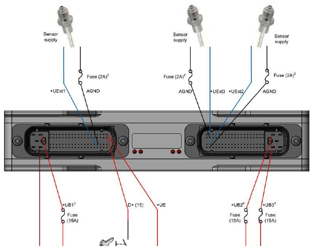
Power connection wiring
Notes:
1. Minimal connections for operating are D+, +UE and GND.
2. Fuse is recommended if short circuit to UBat cannot be excluded.
Attention: Applying this fuse can result in minor precision of applied sensors!
3. +UB1 is needed when 4A-High side outputs are used.
4. +UB2 is needed when 2.5A-High side outputs 1 to 8 are used.
5. +UB3 is needed when 2.5A-High side outputs 9 to 16 are used.
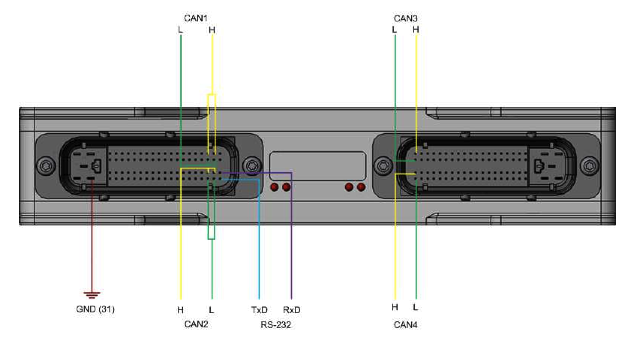
Communication wiring
Notes:
1. Default CAN-Interface for KEFEX-Winflash is CAN1.
2. Standard mode for RS-232 is a three line serial connection (RxD, TxD, Gnd) with no handshake (neither hardware nor software).
3. Avoid short circuits on TxD-lines to GND or +UBat under all circumstances!!!
Mainboard - Hardware - LED assignment
Location
Description
1. Power ON LED: (green)
This LED indicates that all necessary voltages in the ESX-3XL for running the CPU are given. At least +UE and D+ have to be powered on for this.
If this LED doesn't light, the ESX-3XL has no supply or it is damaged.
2. ERROR LED: (red)
This LED shows severe errors which were encountered during POST (Power On Self Test) or while the system is/was running. The following table shows various blink codes for various errors:
| Blink code | Error name | Explanation of error |
|---|---|---|
| LED is off | No error | While there is no error the LED remains off |
| LED is always on | Flash ROM error | System encountered a flash ROM CRC error during booting up. System is halted. Please contact your local sales representative! |
| LED is continously fast flashing (5 Hz) | EEPROM error | System encountered a EEPROM read error during POST or a EEPROM write error during runtime. It is possible that this error can be fixed by using the function x_sys_config_supervisor. If the error persists please contact your local sales representative! |
| LED flashes 3x, then pausing for app. 300ms | UF error | System encountered a low voltage power supply (< 8 V) error during runtime. This error is non-permanent. |
| LED flashes 2x, then pausing for app. 500ms | Usys error | System encountered an error on the system voltages during runtime. This error can be seen for a short time during power up and is non permanent. |
| LED flashes 1x, then pausing for app. 700ms | Watchdog error | System encountered an watchdog error. The watchdog wasn't retriggered in time. |
3. User LED 1: (red/green)
This LED is freely programmable by the user. Look at x_sys_set_led.
4. User LED 2: (red/green)
This LED is freely programmable by the user. Look at x_sys_set_led.
Connectors KS1 KS2
Downloads in English.
IO List
Connection list for the ESX 3XL computer in the AMS
ESX 3XL Connection list (45 KB .xls)
Pictures
AMS (1) Test Cable Harness, KS1
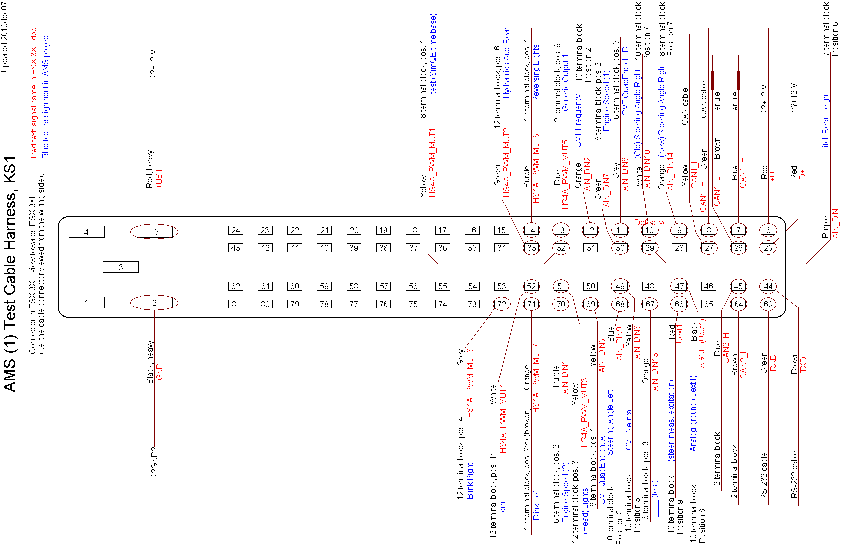
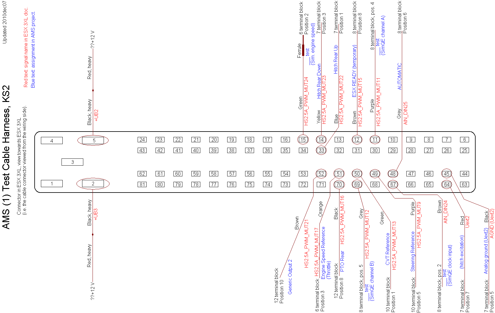
AMS (1) Test Cable Harness, KS2
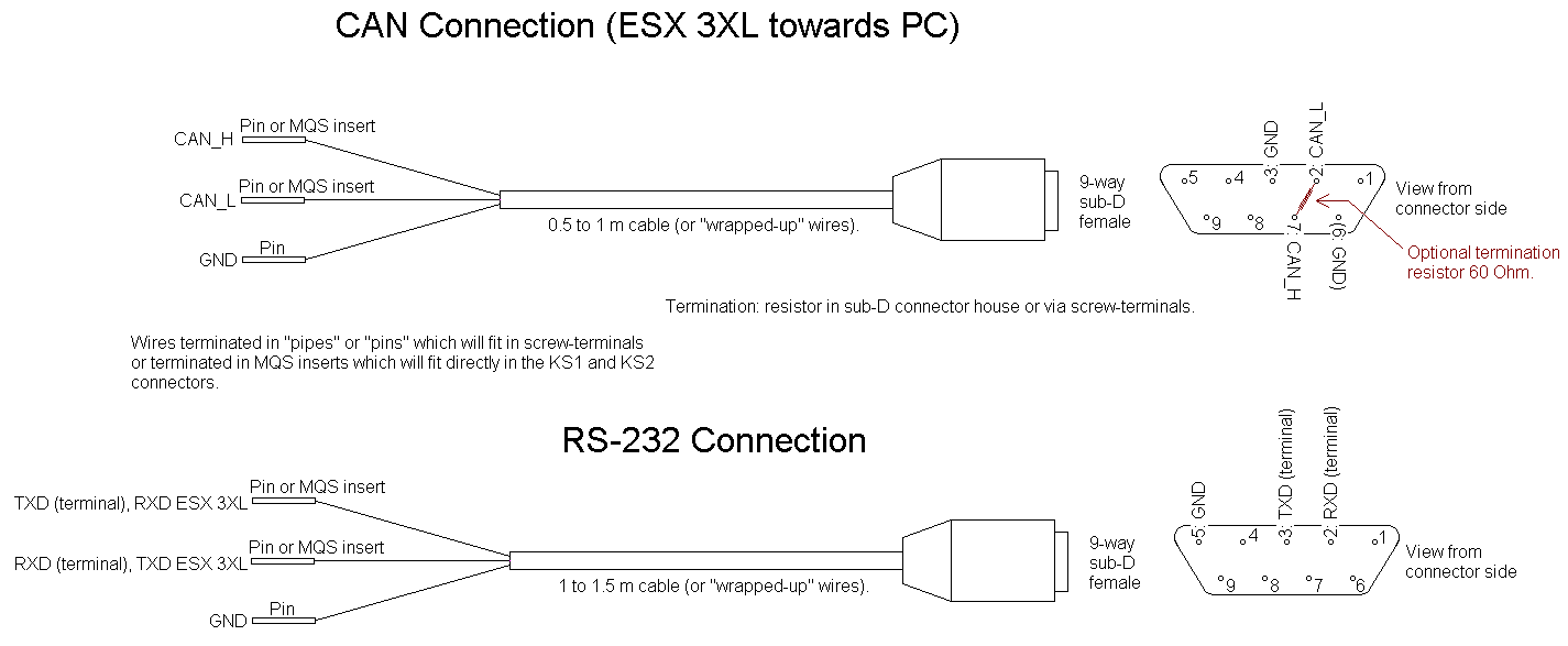
Can Connection - RS232 connection
Connector in ESX 3XL, view towards ESX 3XL

ESX 3XL connectors: Cable connector (socket) seen from front (mating side)

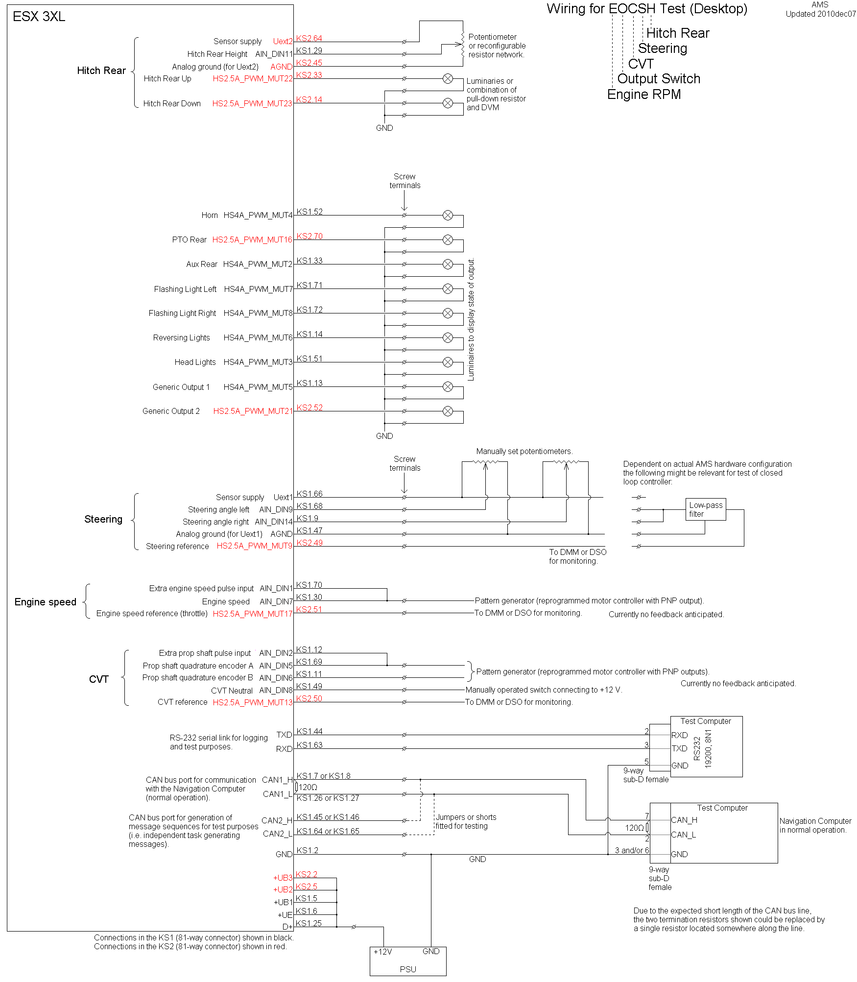
For test of the Engine RPM, Output Switches, CVT and Steering modules something like the following hardware will be needed.
IO for ECS
Inputs:
Channel 1 (KS1 pin 70) : Extra engine speed input. (PNP 12 V).
Channel 2 (KS1 pin 12) : Extra prop shaft (CVT) input. (PNP 12 V).
Channel 5 (KS1 pin 69) : Prop shaft (CVT) quadrature encoder A. (PNP 12 V).
Channel 6 (KS1 pin 11) : Prop shaft (CVT) quadrature encoder B. (PNP 12 V).
Channel 7 (KS1 pin 30) : Engine speed. (PNP 12 V).
??Channel 8 (KS1 pin 49) : CVT Neutral. Switch to 12 V (i.e. PNP type).
Channel 9 (KS1 pin 68) : Steering angle left. (Potentiometer).
Channel 10 (KS1 pin 10) : Steering angle right. (Potentiometer).
Outputs:
Channel 2 (KS1 pin 33) : Aux Rear (hydraulics).
Channel 3 (KS1 pin 51) : Lights (head).
Channel 4 (KS1 pin 52) : Horn.
Channel 6 (KS1 pin 14) : Reversing Lights.
Channel 7 (KS1 pin 71) : Flashing Light Left (indicator light).
Channel 8 (KS1 pin 72) : Flashing Light Right (indicator light).
Channel 9 (KS2 pin 49) : Steering reference.
Channel 13 (KS2 pin 50) : CVT Speed reference.
Channel 16 (KS2 pin 70) : PTO Rear.
Channel 17 (KS2 pin 51) : Engine speed reference.
Sensor supply.
Uext1 (KS1 pin 66) ??Supply for steering angle potentiometers?
AGND (for Uext1) (KS1 pin 47)
Supply for output groups.
+UB1 (KS1 pin 5)
+UB2 (KS2 pin 5)
+UB3 (KS2 pin 2)
RS-232
TXD (KS1 pin 44)
RXD (KS1 pin 63)
CAN1 (interface to NavCom).
CAN1_H (KS1 pin 7 / 8)
CAN1_L (KS1 pin 26 / 27)
  Consider whether both pins should be connected (what would be the easiest
  in case the test pattern generator CAN2 should be connected/disconnected).
CAN2 (generating test pattern (commands)).
CAN2_H (KS1 pin 45 or 46)
CAN2_L (KS1 pin 64 or 65)
  Idea: write task which will output a test pattern - not necessarily listening
  to any reports. If complicated tests (many packets) are needed it seems the
  generation of CAN messages should be automated - the ESX 3XL seems to be the
  only available device which can generate CAN message patterns).
Supply for computer.
GND (KS1 pin 2)
+UE (KS1 pin 6)
D+ (KS1 pin 25) ??Will this be necessary for this test?
??Consider sequencing input for test purposes? The RS-232 or the CAN bus should probably be used instead.


